- 您现在的位置:买卖IC网 > Sheet目录1219 > HC5514XEVAL3 (Intersil)EVAL BOARD TI CODEC MOTHER BOARD
�� �
�
�Application� Note� 9871�
�40�
�1.� Without� power� sharing,� the� on-chip� power� dissipation�
�would� be� 952mW� (Equation� 6).�
�35�
�30�
�25�
�V� BH�
�V� BL�
�2.� With� power� sharing,� the� on-chip� power� dissipation� is�
�412mW� (Equation� 7).� A� power� redistribution� of� 540mW.�
�On-chip� power� dissipation� without� power� sharing� resistor.�
�20�
�15�
�VBH� =� -48V�
�VBL� =� -24V�
�RILim� =� 33.2k� ?�
�P� D� =� (� V� BH� )� (� 30mA� )� +� 38.4mW� +� 13.5mW� –� (� RL� )� (� 30mA� )�
�P� D� =� 952mW�
�2�
�(EQ.� 6)�
�10�
�On-chip� power� dissipation� with� 600� ?� power� sharing� resistor.�
�5�
�V� BL�
�V� BH�
�P� D� =� (� V� BH� )� (� 30mA� )� +� 38.4mW� +� 13.5mW�
�–� (� R� L� )� (� 30mA� )� –� (� R� PS� )� (� 30mA� )�
�0�
�LOOP� RESISTANCE� (� ?� )�
�P� D� =� 412mW�
�2�
�2�
�(EQ.� 7)�
�FIGURE� 3.� BATTERY� SELECTION� (DUAL� SUPPLY� SYSTEMS)�
�The� design� trade-off� in� using� the� power� sharing� resistor� is�
�loop� length� verses� on-chip� power� dissipation.�
�Setup�
�1.� Reference� Test� #1� “Power� Supply� Current� Veri?cation”�
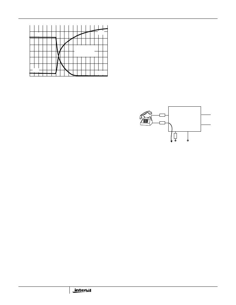
�TIP�
�UniSLIC14�
�V� TX�
�and� the� results� in� Table� 1.�
�Veri?cation�
�RING�
�V� RX�
�1.� Notice� for� the� onhook� condition� (extremely� long� line)� that�
�all� the� current� is� provided� by� V� BH.� This� feature� enables�
�onhook� transmission� on� the� longest� loop� for� a� given�
�battery� voltage.�
�2.� Notice� for� a� 600� ?� load,� the� current� is� shared� by� both� V� BH�
�ON� SHORT� LOOPS,� THE�
�MAJORITY� OF� CURRENT�
�FLOWS� OUT� THE� V� BL� PIN�
�V� BL�
�R� PS�
�-48V�
�V� BH�
�-48V�
�and� V� BL� .� If� tip� and� ring� are� shorted,� then� most� of� the� loop�
�current� will� come� from� V� BL� .�
�3.� Notice� the� same� is� true� for� the� reverse� active� state.�
�Discussion� (Power� Sharing)�
�Power� sharing� is� a� method� of� redistributing� the� power� away�
�from� the� SLIC� in� short� loop� applications.� The� total� system�
�power� is� the� same,� but� the� die� temperature� of� the� SLIC� is�
�much� lower.� Power� sharing� becomes� important� if� the�
�application� has� a� single� battery� supply� (-48V� on� hook�
�requirements� for� faxes� and� modems)� and� the� possibility� of�
�high� loop� currents� (reference� Figure� 4).� This� technique�
�would� prevent� the� SLIC� from� getting� too� hot� and� thermally�
�shutting� down� on� short� loops.�
�The� power� dissipation� in� the� SLIC� is� the� sum� of� the� smaller�
�quiescent� supply� power� and� the� much� larger� power� that�
�results� from� the� loop� current.� The� power� that� results� from� the�
�loop� current� is� the� loop� current� times� the� voltage� across� the�
�SLIC.� The� power� sharing� resistor� (R� PS� )� reduces� the� voltage�
�across� the� SLIC,� and� thereby� the� on-chip� power� dissipation.�
�The� voltage� across� the� SLIC� is� reduced� by� the� voltage� drop�
�across� R� PS� .� This� occurs� because� R� PS� is� in� series� with� the�
�loop� current� and� the� negative� supply.�
�A� mathematical� veri?cation� follows:�
�Given:� V� BH� =� V� BL� =� -48V,� Loop� current� =� 30mA,� R� L� (load�
�across� tip� and� ring)� =� 600� ?� ,� Quiescent� battery� power� =�
�(48V)� (0.8mA)� =� 38.4mW,� Quiescent� VCC� power� =� (5V)�
�(2.7mA)� =� 13.5mW,� Power� sharing� resistor� =� 600� ?� .�
�5�
�FIGURE� 4.� POWER� SHARING� (SINGLE� SUPPLY� SYSTEMS)�
�Test� #6,� Ring� Trip� Veri?cation�
�This� test� will� verify� the� ringing� function� of� the� HC5514X.� A�
�telephone,� a� battery� referenced� AC� signal� source,� and� a�
�BNC� to� banana� adaptor� are� the� only� additional� hardware�
�required� to� complete� the� test.�
�Discussion�
�The� 600� ?� termination� is� not� necessary� for� this� test� since� the�
�phone� provides� this� nominal� impedance� when� offhook.� If� the�
�RSYNC_REV� pin� is� grounded,� the� ring� relay� driver� pin�
�(RRLY)� pin� goes� low� after� the� SLIC� is� placed� in� the� ringing�
�state.� This� will� energize� the� ring� relay.� The� ring� relay�
�disconnects� tip� and� ring� from� the� phone� and� connects� the�
�path� for� the� ringing� signal.� The� D� T� and� D� R� comparator� inputs�
�will� sense� the� ?ow� of� DC� loop� current,� enabling� the� ring� trip�
�comparator� to� sense� when� the� phone� is� either� onhook� or�
�offhook.� When� an� offhook� condition� is� detected,� the�
�HC5514X� will� automatically� disconnect� the� ringing� signal� to�
�the� phone� at� zero� current� crossing.� This� reduces� impulse�
�noise� to� the� system.� Refer� to� the� HC5514� Subscriber� Line�
�Interface� Circuit� electrical� data� sheet� for� more� information�
�about� the� functionality� of� the� ring� trip� detector.�
�Setup�
�1.� Connect� the� power� supplies� to� the� Evaluation� board.�
�2.� Set� V� BH� to� -48V,� V� BL� to� -24V� and� V� CC� to� +5V.�
�发布紧急采购,3分钟左右您将得到回复。
相关PDF资料
HC55185EVAL2
EVALUATION PLATFORM HC55185+T
HE1015
BOOT CIRCUIT BREAKER 1POLE CLEAR
HE1020
BOOT CIRCUIT BREAKER 2POLE CLEAR
HE1050
BOOT CIRCUIT BREAKER 3POLE CLEAR
HE1070
BOOT CIRCUIT BREAKER 3POLE CLEAR
HFW30R-1STE1
HFW30R-1STE1-FFC/FPC CONN
HFW30S-2STE1
HFW30S-2STE1-USING HFW-P5SL
HHG
FUSEHOLDER AUTO INLINE FOR ATC
相关代理商/技术参数
HC5515
制造商:INTERSIL 制造商全称:Intersil Corporation 功能描述:ITU CO/PABX SLIC with Low Power Standby
HC5515_06
制造商:INTERSIL 制造商全称:Intersil Corporation 功能描述:ITU CO/PABX SLIC with Low Power Standby
HC55150
制造商:INTERSIL 制造商全称:Intersil Corporation 功能描述:Low Power Universal SLIC Family
HC55150CB
制造商:Rochester Electronics LLC 功能描述:LOW PWR SLIC,POL REV/METERING,55DB BALANCE - Bulk
HC55150CBZ
功能描述:电信线路管理 IC LW PWR SLIC POLV/MTRING 55DB RoHS:否 制造商:STMicroelectronics 产品:PHY 接口类型:UART 电源电压-最大:18 V 电源电压-最小:8 V 电源电流:30 mA 最大工作温度:+ 85 C 最小工作温度:- 40 C 安装风格:SMD/SMT 封装 / 箱体:VFQFPN-48 封装:Tray
HC55150CM
制造商:Rochester Electronics LLC 功能描述:LOW PWR SLIC,POL REV/METERING,55DB BALANCE - Bulk
HC55150CMZ
功能描述:电信线路管理 IC LW PWR SLIC POLV/MTRING 55DB RoHS:否 制造商:STMicroelectronics 产品:PHY 接口类型:UART 电源电压-最大:18 V 电源电压-最小:8 V 电源电流:30 mA 最大工作温度:+ 85 C 最小工作温度:- 40 C 安装风格:SMD/SMT 封装 / 箱体:VFQFPN-48 封装:Tray
HC55151
制造商:INTERSIL 制造商全称:Intersil Corporation 功能描述:Low Power Universal SLIC Family